01
01 Background
The Major Qualifying Project, or MQP, is a project at WPI in a student's area of study meant to give the student a real-world engineering experience. In my senior year, I chose to build an autonomous ground vehicle for my MQP with Professor Alexander Wyglinski.
With the price of sensors and computing steadily decreasing year after year, affordable self-driving automobiles are starting to become a reality. This MQP aimed to imagine a divergent take on autonomous vehicle technology by challenging modern vision algorithms rather than pursue expensive sensors like LIDAR. Although sensors like LIDAR have dominated recent ventures, their price, bulk, and vulnerable location atop autonomous vehicles could hinder their uptake in the future. As a result, this project sought instead to pursue vision-based object-recognition and navigation. For this project, a 1995 electric golf cart was acquired for prototyping.
The 1995 electric golf cart we modified to be autonomous.
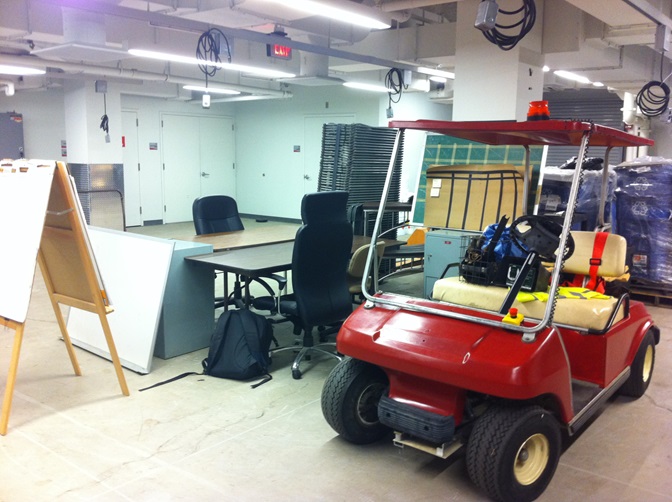
The 1995 electric golf cart we modified to be autonomous.
02
02 Approach
Significant upgrades had to be made to its design in order for it to become autonomous. Because of the large scale of this project, the project was broken down into separate subsystems, each of which were worked on separately to be combined sometime in the future. The different systems requiring modifications are shown below. My work on the project involved the three electromechanical subsystems outlined in orange—the stereoscopic cameras, the automated steering mechanism, and the automated braking mechanism. Each of these subsystems posed its own unique challenges and had to be dealt with differently.
Overview of the different subsystems of the autonomous vehicle.
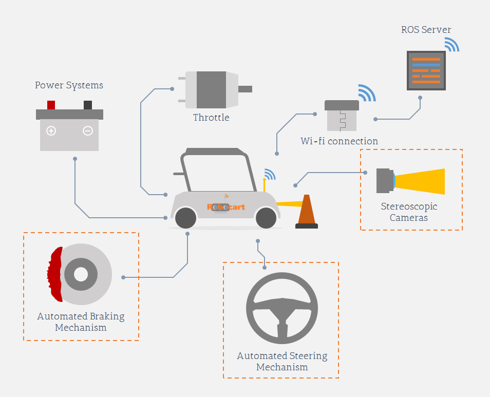
Overview of the different subsystems of the autonomous vehicle.
03
03 Raspberry Pi Camera Mount
Raspberry Pi cameras were used for the steroscopic cameras, since they were cheaply available and readily able to be connected to a wireless network through Raspberry Pi computers. A mounting solution was required for the Raspberry Pi cameras and computers. Creating a mount was more difficult than originally anticipated, since the requirements called for, for example, ensuring that the stereoscopic cameras would always point in exactly the same direction. The final design, after going through five iterations, is shown modeled in CAD below. The red plate holding the Raspberry Pi computers and cameras can be easily removed by pinching a spring-locked mechanism and sliding it out.
The CAD model of the final design of the Raspberry Pi camera mount.
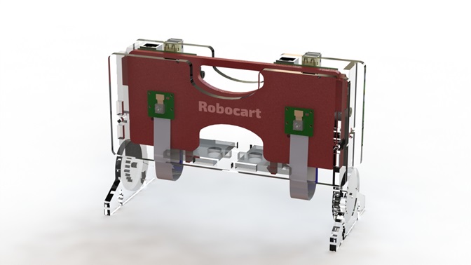
The CAD model of the final design of the Raspberry Pi camera mount.
The final design is shown below; tests showed that the design worked well and the cameras were held rigidly. The adjustable legs allowed us to try attaching the cameras to different locations on the golf cart.
The final Raspberry Pi camera mount attached to the golf cart frame.
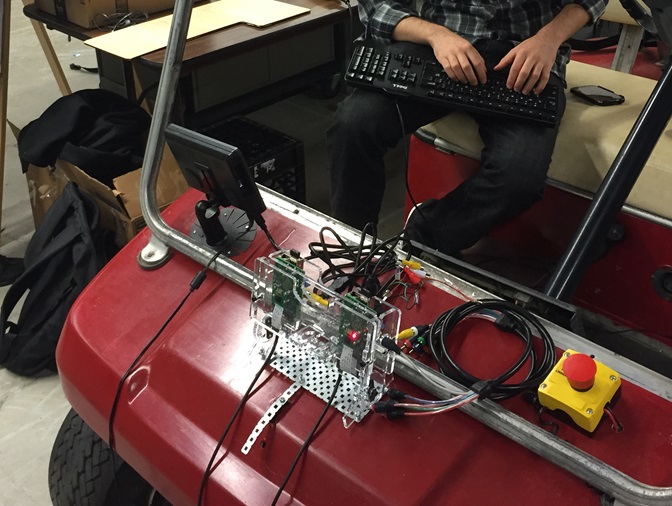
The final Raspberry Pi camera mount attached to the golf cart frame.
04
04 Automated Steering Mechanism
Next, the steering system needed to be modified to allow the computer to control it. This involved attaching a motor to the dashboard of the golf cart (since there was no space under the hood) using a chain and sprocket system. The appropriate torque and speed calculations were done, and a motor was acquired. A multiturn potentiometer was used for position feedback and was attached with its own sprocket. The potentiometer sprocket was chosen to maximize the resolution of the data coming out of the sensor.
Exploded CAD view of the steering assembly attached to the golf cart dashboard.
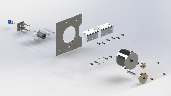
Exploded CAD view of the steering assembly attached to the golf cart dashboard.
Once everything was mounted, the final tests showed the speed and torque of the system had surpassed the requirements. Translucent acrylic plates were placed on either side of the sprockets for aesthetics, to protect the components and the passengers, and to decrease the chance of the chain slipping off the sprockets.
The final design of the automated steering mechanism.
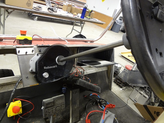
The final design of the automated steering mechanism.
05
05 Automated Braking System
Finally, the brakes on the golf cart were automated to allow the computer to control them. A non-backdrivable van door motor was chosen for its high torque and low speed. For safety, a new mechanism was designed to allow the brake pedal to override the computer control. The design, shown below in CAD, is such that the motor pulls on the red block with a pair of steel ropes. The red block collides with a collar which pulls the hooked rod forward, engaging the brakes. However, the brake pedal can also pull on the hooked rod without fighting against the motor, making the mechanism backdrivable.
A CAD model of the final automated braking system.
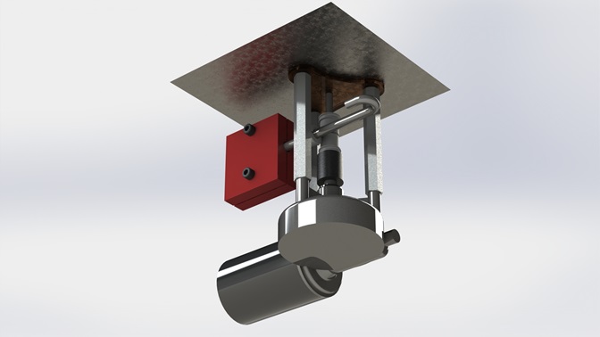
A CAD model of the final automated braking system.
The system was messy and difficult to mount since the golf cart had to be propped up with a car jack, but the final design worked well within the given time and force requirements in testing. The final design is shown mounted to the bottom of the golf cart below.
The final design of the automated braking system.
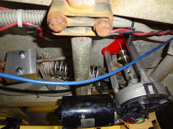
The final design of the automated braking system.